The brief
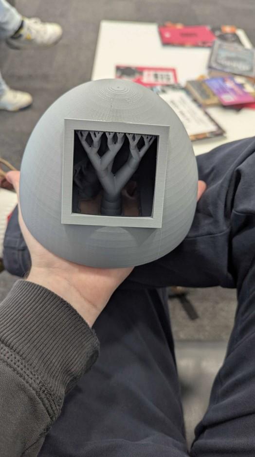
I wanted convincing bass from a portable enclosure while retaining enough control over the electronics to experiment with the sound. The project covered driver selection, acoustic loading, CAD, 3D printing and DSP. Its central experiment was a passive radiator mounted underneath the speaker, with an adjustable gap between it and the surface below.
The enclosure printed successfully and the processing code compiled and uploaded. An unresolved power fault stopped the prototype before verified playback and acoustic measurement, so this is a design and construction study—not a claim of measured performance.
Why small bass is difficult
A driver creates sound by moving air. Its useful low-frequency capability depends not just on diameter but on cone area and linear excursion. Their product gives volume displacement:
For an ideal small source, maintaining the same sound pressure one octave lower requires roughly four times the displacement. Electronic bass boost cannot remove that mechanical demand. Research across 15 commercial speakers helped set expectations: the design had to trade bass extension and maximum output against portability.
Making the enclosure work
A sealed box traps air that behaves like a spring. A port adds a tuned moving mass of air. I chose a passive radiator: an unpowered diaphragm driven by pressure changes inside the enclosure. It can perform a port-like role where a suitably long duct would be awkward to package.
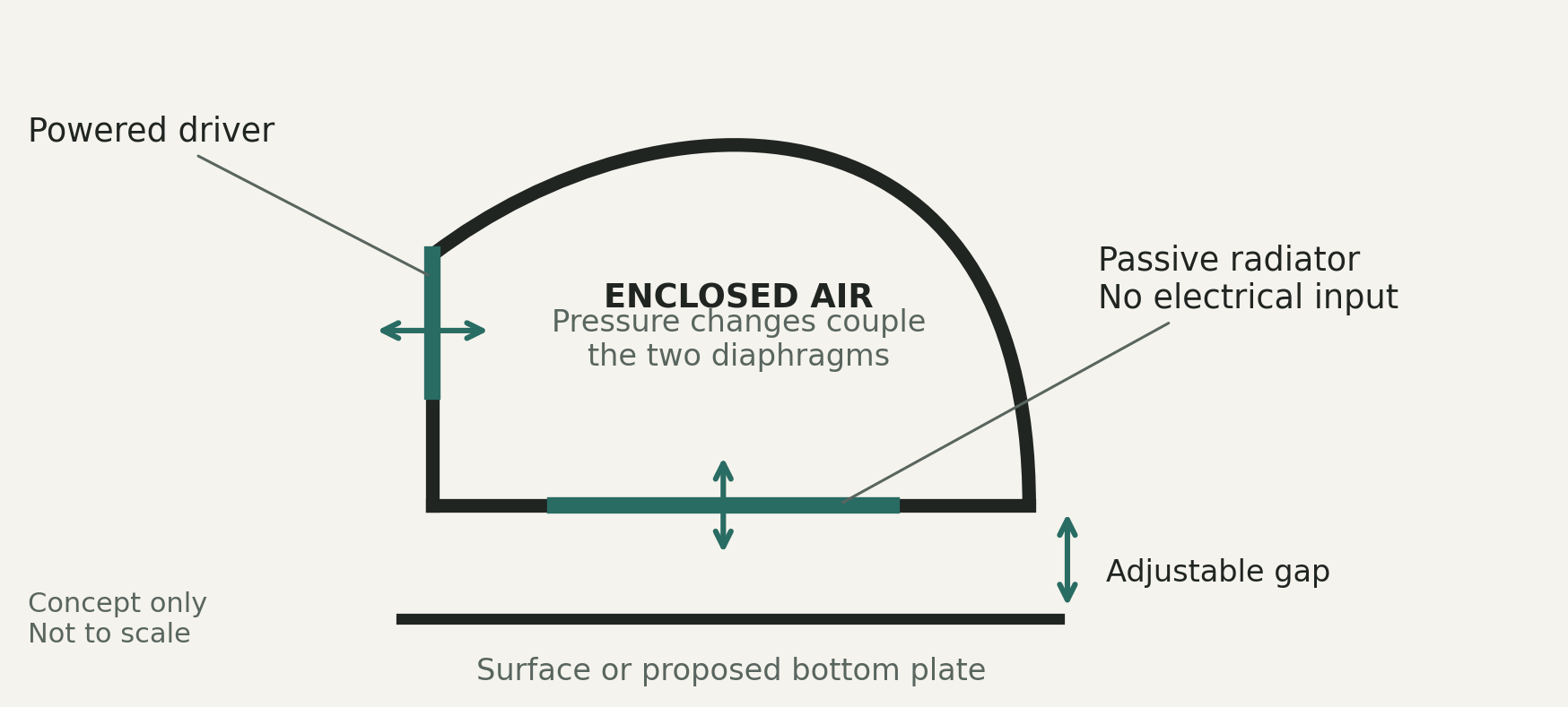
The radiator’s mass, suspension and the enclosure volume determine its behaviour. It can contribute output around tuning and reduce active-driver excursion, but below that region output falls and excessive movement remains a risk.
The adjustable-gap experiment
The curved enclosure left a practical mounting surface on its base. A rigid nearby surface changes the radiator’s acoustic environment, while a narrow gap may change its load. The planned test compared repeatable frequency sweeps at gaps around 1, 2 and 3 cm, with the support surface and microphone arrangement held constant.
Those measurements were not completed. The idea remains a hypothesis for the next build rather than evidence that a smaller gap improves bass.
From ideal design to buildable prototype
The original design specified two Dayton Audio ND91-8 full-range drivers and a DSA135-PR passive radiator. Delivery delays forced a revision to two available 2.5-inch BMR-style units: one powered driver and one converted into an improvised passive radiator by removing its magnet and voice-coil assembly.
That made a mono physical proof of concept possible, but removed the reliable Thiele-Small data needed for confident tuning. The Onshape enclosure had a reported CAD cavity of roughly 0.96 litres before subtracting the volume occupied by internal components.
Signal path and processing
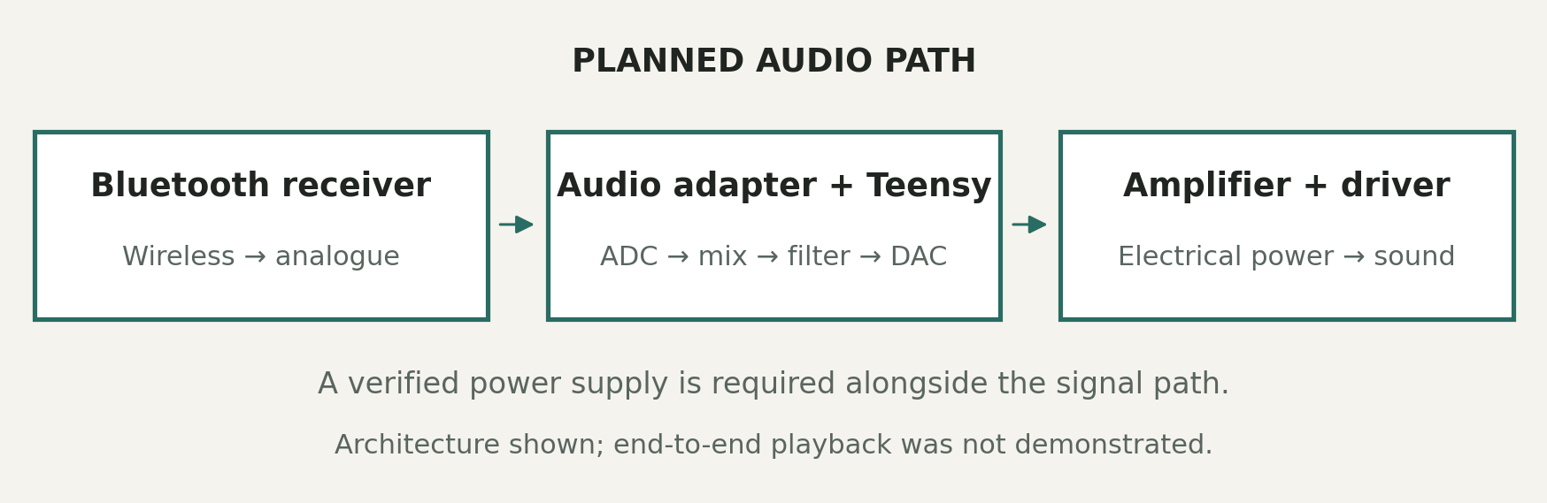
The planned chain used a Bluetooth receiver, Teensy 4.0 and audio adapter, PAM8302 amplifier and the driver. The receiver acquired the signal; the Teensy converted and processed it; the amplifier supplied the power required to move the driver.
The first DSP version mixed stereo to mono with headroom:
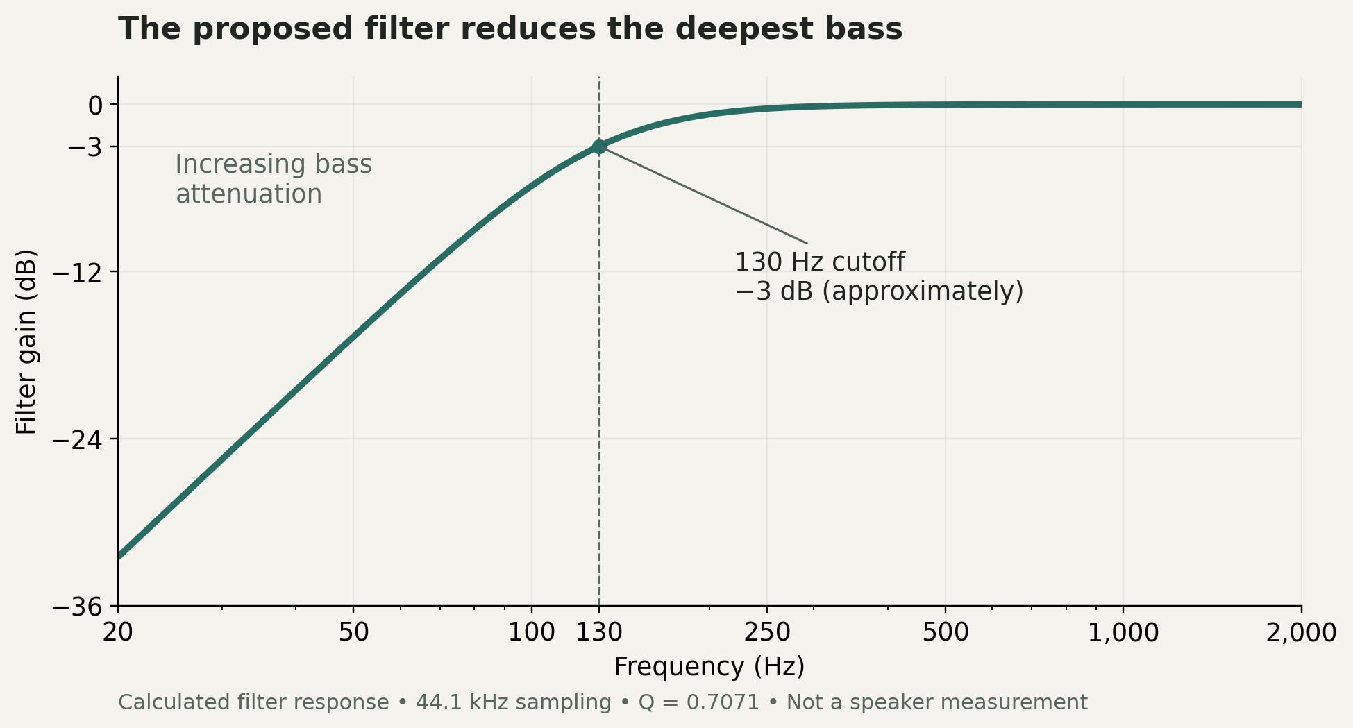
A second-order Butterworth high-pass filter at 130 Hz then reduced the deepest bass demand on the poorly characterised driver. This was a protective starting point, not an optimised response.
Where it stopped
The final blocker was power. The battery plan required appropriate charging and conversion hardware; a power bank was awkward to package; and the external USB-C input did not power the Teensy. Without a multimeter, the failure could not be isolated.
A possible cause was an incomplete USB-C sink arrangement: a source normally needs the correct configuration-channel resistors before supplying power. That remained a plausible diagnosis, not a confirmed one.
Consequently, there was no verified playback, frequency-response curve, maximum-level measurement or radiator-gap comparison. The printed enclosure and uploaded DSP code were genuine outcomes; acoustic performance remained unknown.
What I would change
The next version would begin as a bench prototype. I would verify the supply, bring up each board independently, establish a simple working audio path, then add processing before placing anything in the enclosure.
After sealing and reliable playback, I would run fixed-distance comparative sweeps across the different radiator gaps, followed by higher-level distortion, rattle and excursion checks. The most useful lesson was simple: a plausible acoustic design and successful code still depend on careful systems integration—and the power supply should be tested first.